2004-2008 RX-8 - REPAIR PROCEDURE - RECALL 1017E
A. VEHICLE INSPECTION PROCEDURE
1.
Verify that the vehicle is within the following range:
Model Year
VIN Range
Build Date Range
2004-2008
JM1 FE**** 40 100053 – 140891
From April 10, 2003 through
February 18, 2008
JM1 FE**** 50 140892 – 161178
JM1 FE**** 60 200013 – 207471
JM1 FE**** 70 207473 – 214011
JM1 FE**** 80 214012 – 216619
-
If the vehicle is within the above range, proceed to Step 2.
-
If the vehicle is not within the above range, return vehicle to the customer or inventory.
2.
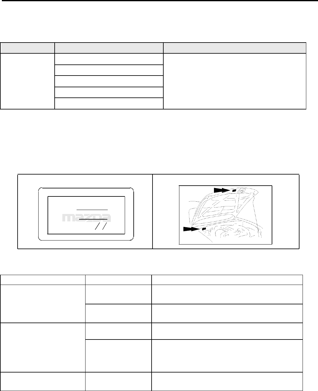
Perform a Warranty Vehicle Inquiry using your eMDCS System and inspect vehicle for Campaign Labels Recall
0516J and 1017E attached to the vehicle’s hood or bulkhead. Refer to eMDCS System - Warranty Vehicle
Inquiry Results
table below.
NOTE: Be sure to verify Recall number as the vehicle may have multiple Recall labels.
CAMPA IGN LABEL
CAMPAIGN NO:
DEALER C ODE:
DATE:
P/N 9999-95-065A-06
1326b
campaign_label
eMDCS System - Warranty Vehicle Inquiry Results:
If eMDCS displays:
Campaign Label is:
Action to perform:
RECALL 1017E OPEN and
RECALL 0516J is not
present
Present
Contact the Warranty Hotline at (877) 727-6626 op-
tion 3 to update vehicle history.
Not present
Proceed to “FUEL PUMP REPLACEMENT
PROCEDURE”.
RECALL 0516J CLOSED
and RECALL 1017E OPEN
Both labels are Present
Contact the Warranty Hotline at (877) 727-6626 op-
tion 3 to update vehicle history.
Not present
Proceed to “FUEL PUMP REPLACEMENT
PROCEDURE PAYING ATTENTION TO THE
NOTES REGARDING 0516J IN THE REPAIR
PROCEDURE
RECALL 0516J is not
displayed
Does not apply
Recall does not apply to this vehicle. Return vehicle
to inventory or customer.
Page 1 of 18
Page 2 of 18
B.
REPAIR PROCEDURE
“Fuel pump Ring recall campaign” and “Fuel Pump Discharge Pipe Crack” - Combined
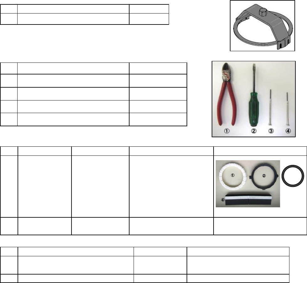
TOOL INFORMATION
Special Tool
No.
Special tool Name
Qty.
①
Fuel Pump Ring Wrench
1
This tool is used at Recall Campaign: Fuel Leak at Fuel Pump Rings
Required tools
No. Tool Name Note
① Diagonal cutting pliers -
② Flathead screwdriver -
③ Small flathead screwdriver (A) 2.3 mm
④ Small flathead screwdriver (B) 2.0 mm
Parts Information 1017E is open and recall 0516J is not displayed in eMDCS
No.
Part Name
Part Number
Component
Remark
①
Fuel pump ring
kit
(union nut)
F1Y1-42-A1X
Fuel pump ring 2pcs
Retainer 2pcs
Fuel Pump Ring Gasket
2pcs
Heat Insulation Pad 2pcs
②
Fuel pump
filter body kit
N3Y1-13ZE0C
Fuel filter body 1pc
Gasket 2pcs
Parts Information – Recall 0516J is closed and 1017E is open
No.
Part Name
Part Number
Component
①
Fuel pump filter body kit
N3Y1-13ZE0C
Fuel filter body 1pc
Gasket 2pcs
②
Fuel pump ring gasket
BN8F-42166
1pcs (Need main side only)
PROCEDURE
1. Perform the fuel line safety procedure.
WARNING
Fuel is extremely flammable. Always keep sparks and flame away from fuel. Ignition may cause death
or serious injury, or damage to equipment.
Fuel line spills and leakage from the pressurized fuel system are dangerous. Fuel can ignite and cause
serious injury or death and damage. Fuel can also irritate skin and eyes. To prevent this, always
complete the "Fuel Line Safety Procedure".
A person charged with static electricity could cause a fire or explosion, resulting in death or serious
injury. Before performing work on the fuel system, discharge static electricity by touching the vehicle
body.
CAUTION
If there is foreign material on the connecting area of the quick release connector, it might damage the
connector or fuel pipe. To prevent this, when the quick release connector has been disconnected,
clean the connecting area before reconnecting it.
①
③
Page 3 of 18
Fuel Line Safety Procedure
1) Remove the fuel-filler cap to release the pressure inside the fuel tank.
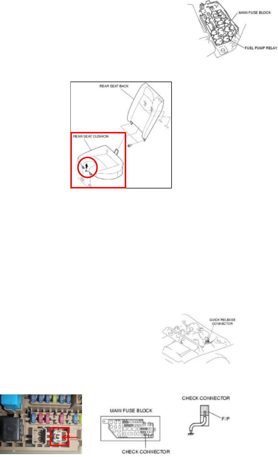
2) Remove the fuel pump relay.
3) Start the engine.
4) After the engine stalls, crank the engine several times.
5) Turn the ignition switch to the LOCK position.
6) Install the fuel pump relay.
2. Remove the rear seat cushion.(Both right and left sides)
Lift the point A in the direction of the arrow and then remove the rear seat cushion.
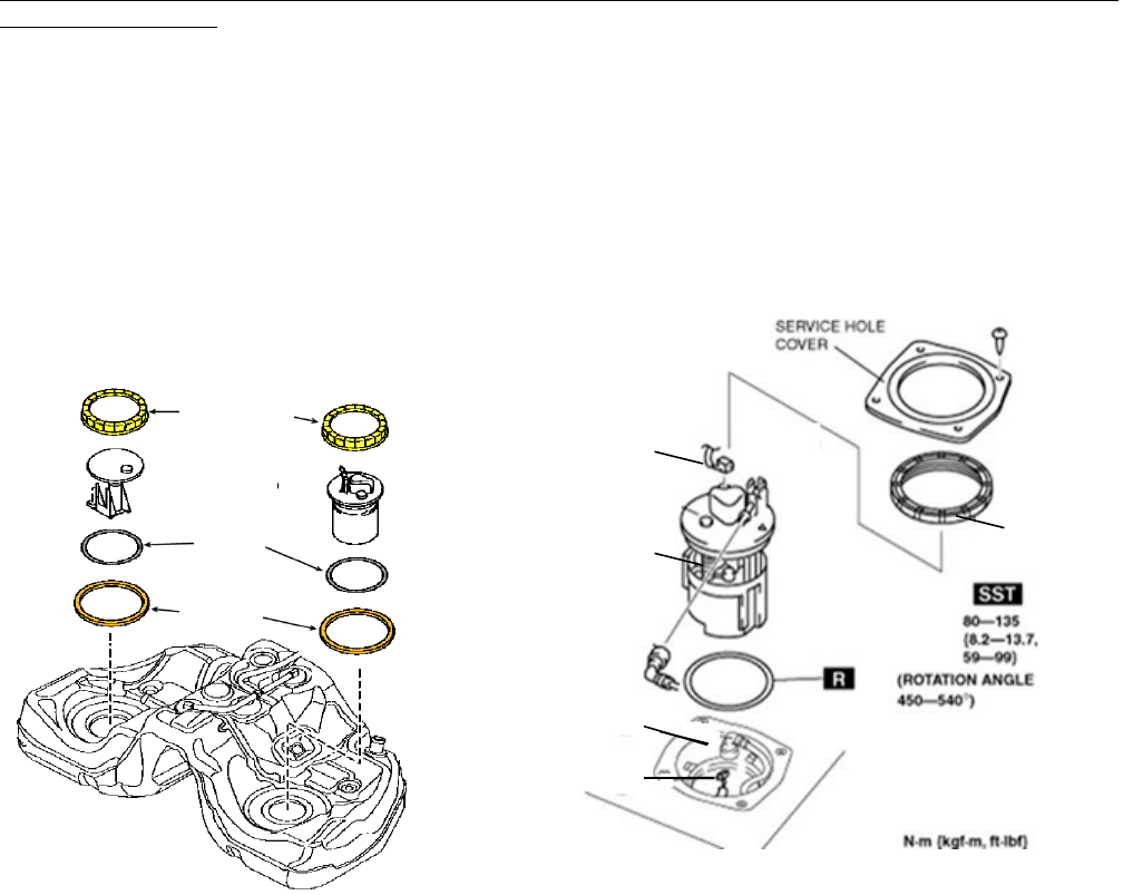
3. Remove the service-hole cover.
4. Check the fuel gauge indication.
NOTE: If the fuel gauge indicates 1/4 or less, go to Step 6 skipping Step 5.
5. Drain fuel from the fuel tank. (Only when the fuel gauge indicates 1/4 or more)
CAUTION
When the fuel gauge indicates 1/4 or more, the fuel level is higher than the installation surface of the
fuel pump and the fuel suction pipe bracket. Due to this condition, fuel may spill or leak out when
performing next steps. Therefore, make sure to drain out fuel until the fuel tank becomes 1/4 full or less
(according to the fuel gauge indication).
WARNING
A person charged with static electricity could cause a fire or explosion, resulting in death or serious
injury. Before draining fuel, make sure to discharge static electricity by touching the vehicle body.
1) Disconnect the quick release connector (engine
compartment side).
2) Attach a long hose to the disconnected fuel pipe and drain the fuel into a proper receptacle.
3) Ground the check connector terminal F/P to the body using a jumper wire.
Page 4 of 18
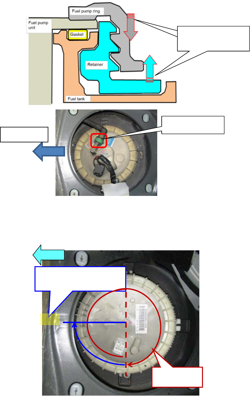
Fuel Pump
Ring
Fuel Pump
Unit (Main)
Fuel suction
P
ipe Bracket
(Sub)
Gasket
Retainer
CAUTION
Shorting a wrong terminal of the check connector may cause electrical malfunctions. Make sure to short
only the specified terminal.
4) Turn the ignition switch to the ON position and operate the fuel pump.
CAUTION
The fuel pump may malfunction if it is operated without any fuel in the fuel tank (fuel pump idling).
Constantly monitor the amount of fuel being discharged and immediately stop operation of the pump
when essentially no fuel is being discharged.
5) When essentially no fuel is being discharged from the hose, turn the ignition switch to the LOCK
position.
NOTE
When operating the fuel pump with a full fuel tank, fuel discharge will become erratic after approximately
10 min, but will continue for approximately 10 min more (and barely any fuel will be discharged). At this
time the fuel gauge needle will be at the 1/4 position.
6) Disconnect the jumper wire.
6. Disconnect the negative battery cable.
7. Replace the inner parts of fuel pump (main side) and the fuel pump ring (both sides) with a modified one,
along with the gasket and retainer. NOTE: If Recall 0516J (Fuel Leak at Fuel Pump Rings) is closed, the
retainer and fuel pump ring will be reused.
CAUTION
DO NOT LEAVE THE FUEL TANK FOR A LONG TIME IN CONDITION THAT THE FUEL PUMP RING
IS NOT INSTALLED.
If the fuel tank is left for a long time without the fuel pump ring installed, the shape of the fuel tank where
the fuel pump ring is installed could be deformed by swelling, causing it difficult to install the fuel pump
ring.
Therefore, install a new one immediately after removing the old fuel pump ring. To complete the
replacement in a short time;
・Complete the replacement at one side first then proceed to other side.
・Put replacement parts near the vehicle before starting the replacement.
・When you remove the fuel pump ring to disassemble/assemble the fuel pump unit, immediately
reinstall it again temporary to the fuel tank side by rotating with hands (No need to use SST).
Connector
Fuel pump unit
Fuel Pump Ring
Connector
Fuel suction pipe

Page 5 of 18
【
Main side (Fuel pump unit side)
】
1) Disconnect the connectors.
2) Disconnect the quick connector. (Fuel hose)
3) Remove the fuel pump ring using SST (Fuel Pump Ring Wrench).
NOTE: Fit the groove of the SST into the rib of the fuel pump ring
CAUTION
・The fuel pump ring could be damaged if the SST is used with any play between the fuel pump ring and
the SST. Securely attach the SST so that there is no gap between the SST tabs and the side of the fuel
pump ring.
・The fuel suction pipe and harness might be damaged, if the fuel pump unit is lifted too much. Make
sure to lift the pump only a small amount.
・When removing the fuel pump ring, be careful not making the retainer lift up. Otherwise, they will rotate
together and the fuel pump ring will not be removed.
4) Remove the fuel pump unit assembly.
5) Disassembly/Assembly the fuel pump unit according to <FUEL
PUMP UNIT DISASSEMBLY/ASSEMBLY>
CAUTION
After removing the fuel pump ring, immediately reinstall it again
temporary to the fuel tank side by rotating with hands (No need to
use SST). This is to prevent deformation by swelling at installing
portion of fuel tank while disassembling/assembling the fuel pump
unit.
SST (Fuel Pump Ring Wrench)
Page 6 of 18
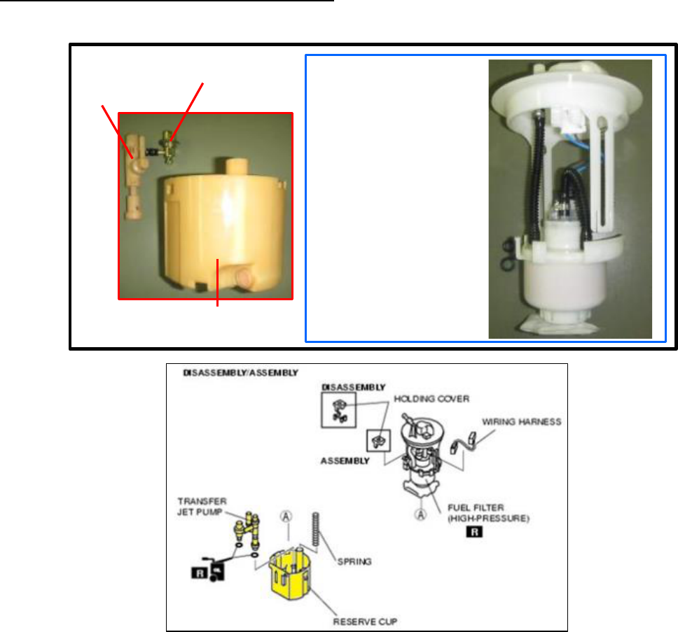
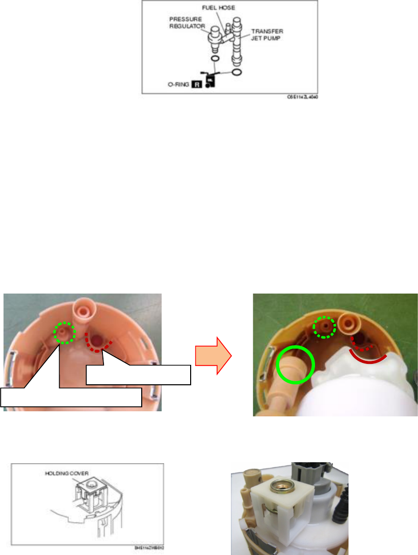
FUEL PUMP UNIT DISASSEMBLY/ASSEMBLY
Parts Information
Warning
Fuel line spills and leakage are dangerous. Fuel can ignite and cause serious injuries or death and
damage. Fuel can also irritate skin and eyes. To prevent this, do not damage the sealing surface of the
fuel pump unit when removing or installing.
Caution
Do not touch the fuel pump discharge pipe unless it is necessary. If servicing is needed, be careful not to
damage the pipe with tools or other objects, or by applying lateral stress. If the pipe is damaged, it may
cause fuel leakage or a fuel pump operation malfunction.
Be careful not to damage the pressure regulator or fuel hose. If it is damaged, it may cause fuel
leakage.
When any parts are removed, be careful that no foreign materials penetrate the part. Otherwise it may
cause a fuel pump unit operation malfunction.
Protect any removed parts using rubber matting to prevent damage. Furthermore, if a part has been
dropped, do not reuse it, replace it with a new one.
Do not use any textile products such as cotton work gloves. If used, fabric may get caught in the fuel
pump or pressure regulator causing a fuel pump unit operation malfunction.
Do not touch the flange seal side of the set plate. If it is damaged or foreign material adheres, it may
cause fuel leakage.
When removing foreign material inside the reserve cup, use fuel for flushing. If foreign material is
removed with air, it may penetrate into the jet pump pressure regulator.
REUSE
Wiring Harness
Fuel Filter
(High-pressure)
Holding cover
Fuel pump
O-ring
(Pressure regulator side)
Reserve cup
(Reuse)
Transfer
jet pump
(Reuse)
Pressure
regulator
(Reuse)
KIT COMPORNENT
REUSE
REUSE
O-ring
(Transfer jet pump side)

Page 7 of 18
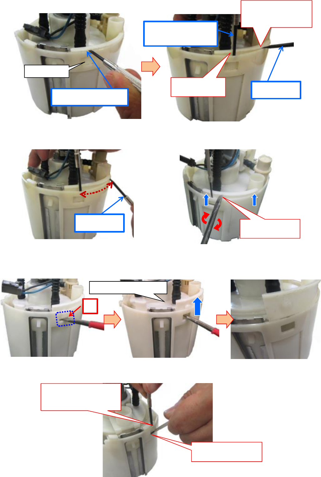
<DISASSEMBLY>
1. Remove the arm part of the set plate.
2. Disconnect the fuel pump connector.
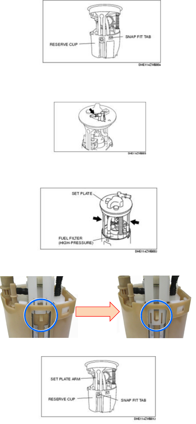
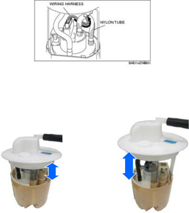
3. Cut the nylon tube as shown below, then remove the set plate.
4. Remove the fuel pump, fuel filter, pressure regulator and
transfer jet pump as a single unit from the reserve cup while
pressing the snap fit tab using a flathead screwdriver.
CAUTION
When disengaging the snap fit tab, don’t hold the reserve cap
as shown below. This is to avoid injury when small flathead
screw driver slips and comes down unintentionally.
Nylon Tube
Set plate
Page 8 of 18
1) Insert the small flathead screwdriver (B) as shown below.
2) Pull up the fuel pump while disengaging the snap fit tab with small flathead screwdriver (A).
3) Insert the flathead screwdriver to clearance (A) as shown below, then pull up the fuel filter
(high-pressure).
4) In the same way as the other side, insert the small flathead screwdriver and pull up the fuel filter.
Rotate the flathead
screwdriver.
A
Snap Fit Tab
Insert the small flathead
screwdriver (B)
Widen the clearance
by using small
flathead screwdriver
Small flathead
screwdriver (A)
Disengage the snap fit
tab with small flathead
screw driver (B)
Disengage the
snap fit tab.
Small flathead
screwdriver (A)
Fuel filter (High-pressure)
Widen the clearance by
using small flathead
screwdriver (A).
Pull up the fuel pump
and filter.
Page 9 of 18
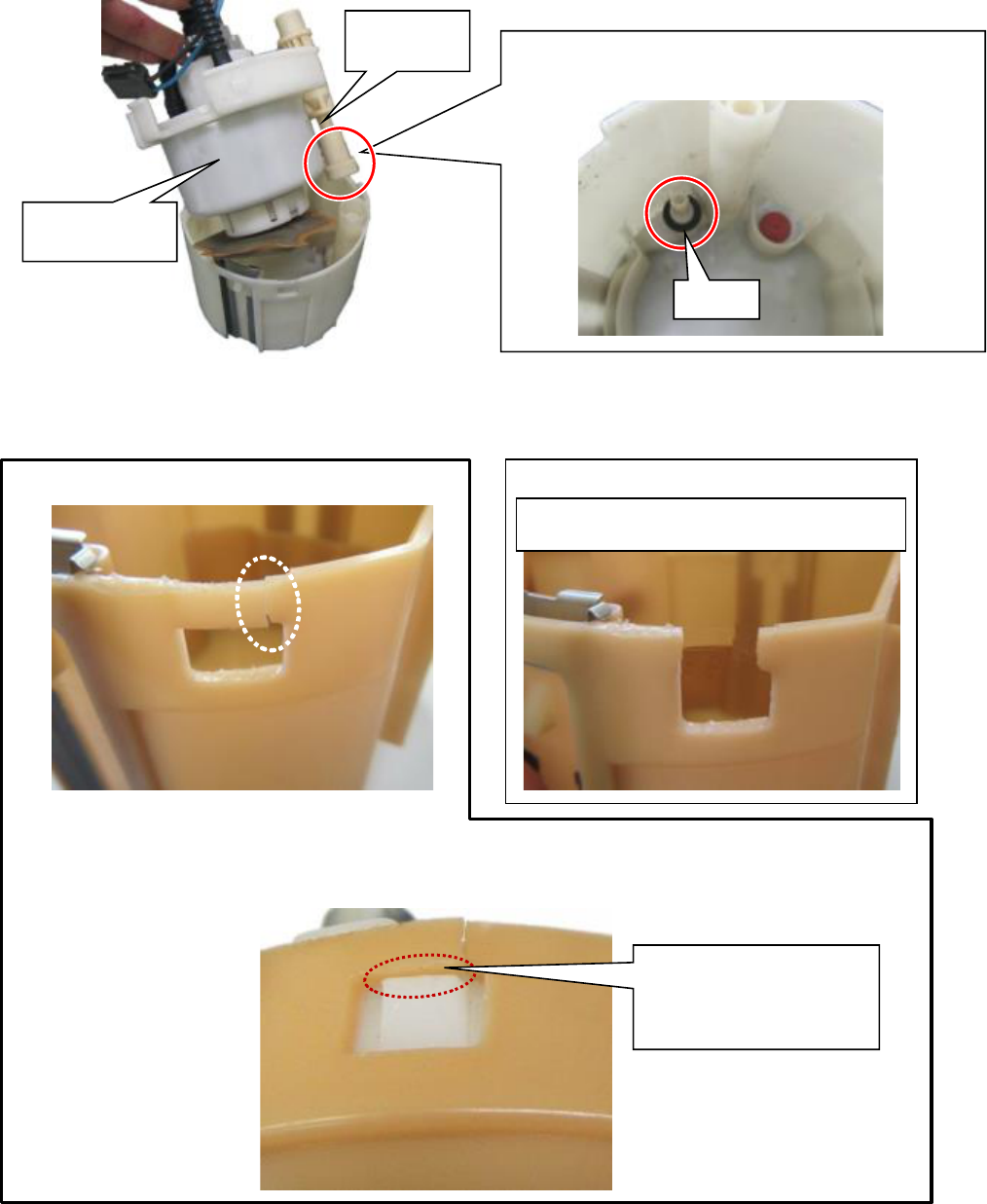
5) Remove the fuel filter (high-pressure), pressure regulator and transfer jet pump as a single unit
from the reserve cup.
NOTE: Verify that the reserve cup is not split, chipped, or bent.
<Reusability Judgment>
When the reserve cup is damaged, judge whether to reuse it depending on the damage condition.
【
Crack
】:
Reusable
【
Missing
】:
Not reusable
NOTE:
The following photo shows that fuel pump and filter are installed to reserve cup which has
cracked.
If the O-ring is remained on the reserve cup side,
remove the O-ring. (Discard the removed O-ring)
This is reusable because
s
nap fit tab is held by
reserve cup which has
crack.
Fuel filter
(high-pressure)
Transfer jet
pump
O-ring
Need to replace the fuel pump (N3H1-13-35ZG)
w ith new one.
Page 10 of 18
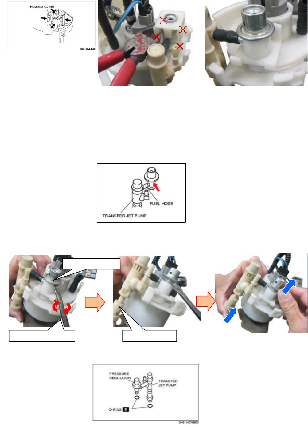
5. Cut the four legs located under the pressure regulator holding cover as shown below.
NOTE: Discard the removed pressure regulator holding cover.
6.Remove the pressure regulator and transfer jet pump from the fuel filter (high-pressure) by using the
flathead screwdriver.
CAUTION
Do not pull out the fuel hose located between the pressure regulator and transfer jet pump. Do
not forcedly rotate or bend it, or it could damage the sealing of the fuel hose (press fit area), or
cause pipe breakage or splitting. In addition, if the fuel hose is buckled and fuel flow distortion
occurs, it may cause jet pump performance deterioration.
NOTE
Inserting the tip of the flathead screwdriver into the position indicated in the figure, rotate the
screwdriver to pry up the pressure regulator slightly.
7. Remove the O-rings from the transfer jet pump and pressure regulator.
Flathead screwdriver Transfer jet pump
Pressure regulator
Page 11 of 18
<ASSEMBLY>
CAUTION
Be careful not to damage the O-ring. If it is damaged, sealing damage might occur, causing fuel
leakage.
1. Apply clean engine oil to the new O-rings.
2. Install a new O-ring to the pressure regulator.
3. Install a new O-ring to the transfer jet pump.
CAUTION
Do not pull out the fuel hose between the pressure regulator and transfer jet pump. In addition, do not
forcibly rotate or bend it, or it may cause damage to the fuel hose sealing or pipe breakage/splitting. If
the fuel hose is buckled and fuel flow distortion occurs, it may cause jet pump performance
deterioration.
4. Install the transfer jet pump and pressure regulator to modified fuel filter (high-pressure).
5. Install the fuel filter (high-pressure), pressure regulator and transfer jet pump as a single unit to the
reserve cup.
6. Engage the snap fit tab and reserve cup, and verify that they are properly engaged.
7. Install the pressure regulator holding cover with new one and verify that the snap fit tab is properly
engaged.
8. Perform the following procedure to install the set plate to the reserve cup.
NOTE: Reuse the spring by removing from old set plate.
Mounting of transfer jet pump
Mounting of fuel filter
Page 12 of 18
CAUTION
Do not grasp the pipe located on the upper surface of the set plate. The pipe may be damaged causing
fuel leakage.
CAUTION
Be careful not to break the set plate arm by applying excessive pressure. If it is broken, it may cause a
fuel pump unit operation malfunction.
1) Insert the set plate arm to the reserve cup.
2) Engage the snap fit tab and set plate arm, and verify that they are properly engaged.
Page 13 of 18
9. Route the wiring harness under the nylon tube.
10. Connect the fuel pump connector.
11. Press the set plate to expand/contract the fuel pump unit, and inspect it for the following:
The fuel pump connector wiring harness is not pinched into the pressure regulator holding cover.
12. Inspect the following and verify that each part is normal.
・Missing part
・Engagement condition of snap fit areas
・Splitting, chipping, bending, and cracking in each part
・Wiring harness routing
・Connector condition
Page 14 of 18
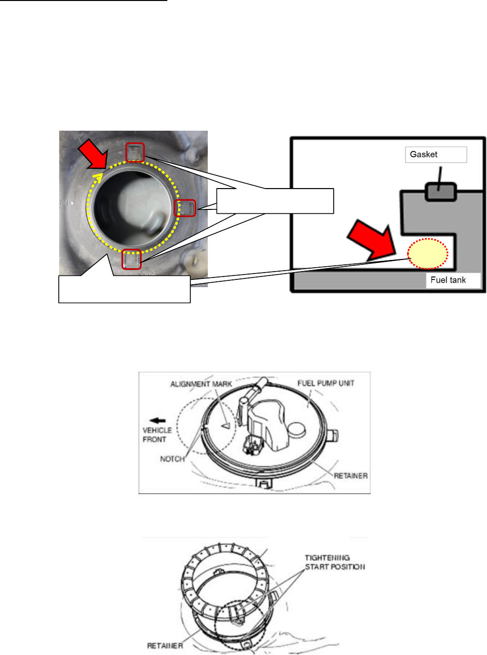
FUEL PUMP UNIT INSTALLATION
1. Replace the retainer and gasket with new ones.
NOTE: If Recall 0516J (Fuel Leak at Fuel Pump Rings) is closed, the retainer and fuel pump ring will be
reused.
CAUTION
Before installing the retainer, clean up the retainer fixing/installing portions of fuel tank (Sand or dust
might be accumulated).
2. Install the modified fuel pump ring.
1) Align the fuel pump unit alignment mark and the retainer notch as shown in the figure.
2) Align the positions of the fuel pump ring and retainer as shown in the figure, and tighten them one full
rotation by hand.
NOTE
If the retainer and fuel pump ring cannot be tightened by hand, remove the fuel pump ring, verify that
there is no damage or misalignment on the retainer and fuel pump ring, and then tighten again.
Fuel Pump Ring
Clean 3 fixing portions
Clean all around the
installing portion.
Clean 3 fixing portions Clean 3 fixing portions
Page 15 of 18
CAUTION
・The fuel pump ring could be damaged if the SST is used with any play between the fuel pump ring and
the SST. Securely attach the SST so that there is no gap between the SST tabs and the side of the fuel
pump ring.
・When tightening the fuel pump ring, be careful not making the retainer lift up. If the retainer comes off
from fixing portions, the retainer spreads, the thread jams, and it reaches to specified torque before
rotating to specified position “☆”.
3. While keeping the alignment mark and the retainer notch aligned, tighten the fuel pump ring to the rotation
angle and specified torque using the SST.
Rotation angle 90-180° 【Total angle for Step 2) and Step 3) is 450-540°】
Fuel pump ring tightening torque 80-135 N· m {8.2-13.7 kgf·m, 59-99 ft·lbf}
One full rotation
by hand
Tighten so the Start position (3
ribs) comes
to mark ”☆” using
SST.
“☆”
Photo is Sub side
Front
When tightening the fuel
pump ring, the retainer
will be lifted up.
Vehicle Front
This fixing portion will
be easy to lift up.

Page 16 of 18
[Sub side]
① Disconnect the connector.
② Remove the fuel pump ring using SST (Fuel
Pump Ring Wrench)
③ Replace the retainer and gasket with new ones.
④ Install the modified fuel pump ring with the same
procedure as the main side.
4. Perform “Fuel Leak Inspection” after the fuel pump unit Installation
1) Start driving the vehicle from a standstill or brake suddenly 5-6 times at a low speed.
2) Stop the vehicle and verify from inside the vehicle that there is no fuel leakage around the fuel pump
ring and quick connector.
NOTE: If Recall 0516J (Fuel Leak at Fuel Pump Rings) is closed, skip the next step 1 (heat insulation
pads installation), and proceed to the step 2.
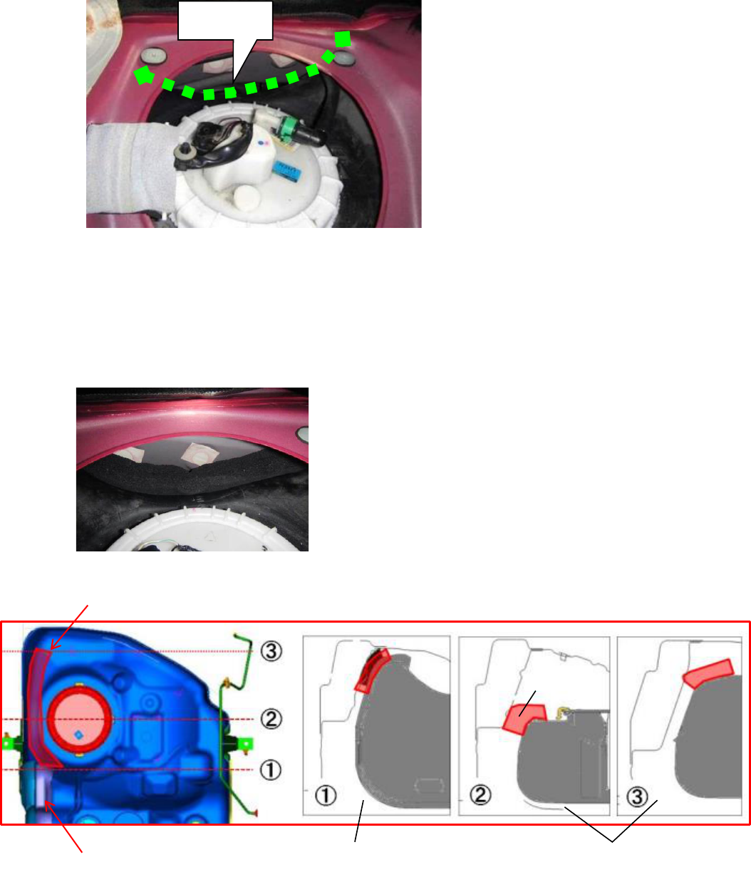
HEAT INSULATION PADS INSTALLATION
1. Attach two heat insulation pads to the fuel tank.
Confirm that there is no
fuel leakage all around the
fuel pump ring.
Confirm that there is no
fuel leakage around the
quick connector.
Heat Insulation Pad
Backing Tape
Pad
:300×60×30 (mm)
Existing Pad
New pads
Page 17 of 18
① Clean the fuel tank where the pad will be attached.
② Remove the backing tape and attach the pad to the fuel tank as shown below.
NOTE
• Attach the pad so it connects without clearance to the existing pad in the central portion of the
fuel tank.
Paste the pad onto the tank without clearance between the body and the tank.
After pasting the pads, confirm that the tape is stuck securely.
【Image how to paste the pads】
③ Attach the pad on the sub side repeating Steps ① - ②.
2. Install the service hole cover with four (4) screws.
3. Install the rear seat cushion.
Cleaning
Existing Pad
New pads
Paste pad without clearance to the
existing pad in the central portion
Paste pad without clearance
between body and fuel tank.
Fuel tank
Body
Pad
Page 18 of 18
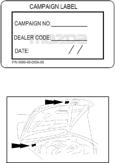
C. CAMPAIGN LABEL INSTALLATION
1. Fill out a blue “Campaign Label” (9999-95-065A-06) with Campaign No: “1017E”, your dealer code,
today’s
date.
2. Affix it to the hood or bulkhead as shown:
campaign_label
3. Return the vehicle to customer.
